CANopenIA System on Module (SoM) for Stand-Alone Operation
CANopen SoM (System on Module) implementations from different vendors provide instant access to digital and analog input and output data as they directly implement entire device profiles. These plug-in modules keep the development time of a CANopen device to a minimum.
| Device Profile | I/O Signals | Buy at esacademystore.eu |
|---|---|---|
| CiA 401, Generic I/O, Joystick | up to 28 digital (in or out), up to 4 on-chip analog in (10bit), up to 4 external analog in (12bit), up to 4 external analog out (12bit), serial remote access |
EmSA's (original ESSolution) |
| CiA 401, Generic I/O and CANopen FD |
8 digital in, 8 digital out up to 13 analog in, up to 4 analog out |
PEAK System's MicroMod FD |
| CiA 447, Generic I/O | up to 28 digital (in or out) up to 8 on chip analog, optional external analog |
PEAK System's SVMII-447 |
The CANopenIA-M0 SoM
The CANopenIA-M0 system on module implements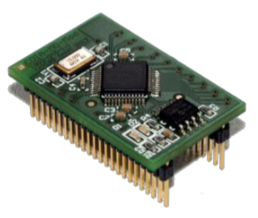 the CANopen protocol compliant to the CiA standards
- CiA301 version 4.2 (CANopen application layer and communication profile),
- CiA305 version 2.2.14 (Layer setting services and protocols) and
- CiA401 version 3.0 (Device profile for generic I/O modules, joysticks).
The CANopenIA-M0 is based on the NXP LPC11C24 32-bit micro controller (ARM Cortex M0). This is a derivative with integrated CAN transceiver which minimizes the external components needed around the protocol chip. The Cortex architecture in conjunction with the optimized firmware design results in a very high performance. Internal processing times between I/O and CAN are down to 15 micro seconds.
This high performant and ready to use CANopen solution is available as a chip or as a module. The module has the chip's glue logic for clock generation, a serial EEPROM to store the configuration data and two LEDs to signal the CANopen state. Entries in the object dictionary, the I/O ports and the SDO and PDO behavior CAN be configured with a provided setup utility. Advanced configurations can be generated with the CANopen Architect editor for Object Dictionaries and EDS files.
The CANopenIA-M0 allows integration of the CANopenIA-M0 chip functions in user’s hardware without taking care about clock generation, transceivers, EEPROM hardware and the status and error indication. The module can easily be implemented in user’s hardware with a two row 48 pin connector. The connector has 1.27mm grid with two rows of 24 pins each.
CANopenIA-M0 Chip Features
- 48-pin LQFP package (9 x 9 mm2)
- Industrial temperature (–40 to 85 °C) range
- 12 MHz external oscillator leads to an internal operating frequency of 48 MHz
- I2C interface to connect the configuration EEPROM
- Internal ADC converter, 8bit resolution
- Two SPI interfaces supporting external D/A and A/D converters
CANopenIA-M0 CAN Features
- The fast and high-performant internal CAN controller works with 32 bit message objects and supports all CANopen data rates up to 1 Mbps
- CANopen protocol implemented in flash
- Up to four transmit process data objects (TPDO)
- Up to four receive process data objects (RPDO)
- Transmission types configurable by SDO access to object dictionary
- Fast response times down to 15 μs due to the architecture optimized CANopen implementation
CANopenIA-M0 Starter Kit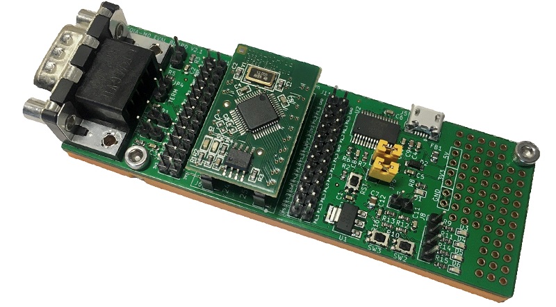
- One CANopenIA-M0 module, plugged into the board
- One male CAN connectors with a switchable terminating resistor
- One USB mini connector (powering the board and for remote access via serial port)
- Pair of jumpers to enable/disable connection of the remote access serial port
- All 48 pins of the module available on marked standard 2.54mm header rows
- 2 generic IN signals (switches) and 4 generic OUT signals (switches) connectable to any pin
For configuration and test any PEAK PCAN-USB PC interface is required.
For testing a CANopen Monitor such as CANopen Magic should be used.
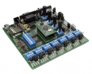 CANopenIA-M0 Advanced Evaluation Board
The evaluation board is intended for advanced evaluations. It provides:
- Two CAN connectors with a switchable terminating resistor
- DIP switches for setting baud rate and node ID
- 28 LEDs to signal the state of the binary output port pins
- 28 switches to stimulate the binary input port pins
- 4 Potentiometer to stimulate either the internal or the external ADC ports
- 4 LEDs to signal the output voltage on the external DAC ports
CANopenIA-M0 Setup Utility
With the CANopenIA-M0 Setup utility all features supported by the CANopenIA-M0 chip are configured in a very easy manner. The setup utility generates a data set to be downloaded to the chip and a device configuration file which can be read by third party CANopen configuration tools.
For configuration and test any PEAK PCAN-USB PC interface is required.
For testing a CANopen Monitor such as CANopen Magic should be used.
CANopenIA-M0 Downloads
- User manual with datasheet information
- CANopenIA-M0 Starter Kit schematics
- Archive with example configurations, EDS, Remote Access application
- CANopenIA configuration and setup utility
- CANopen Architect Mini for advanced configurations
CANopenIA-M0 Training Videos
")
")