CANopenIA Stand-Alone Mode
CANopenIA solutions implementing the stand-alone mode directly implement an entire CANopen Device or Application Profile including both CANopen and application code. These implementations provide the fastest design cycles, as the modules or chips directly implement complete CANopen devices.
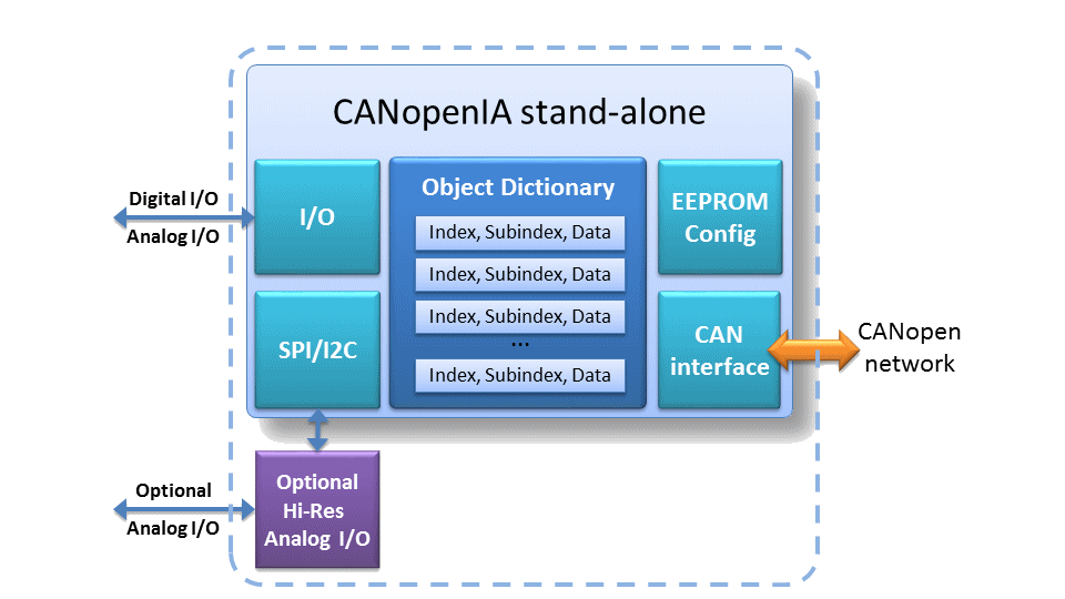
The block diagram above shows the components of a CANopenIA stand-alone system. Digital and analog inputs and outputs are provided as they are available in the specific CANopenIA hardware (microcontroller used). Optional high-resolution analog components might be available via SPI or I2C interface. How the process and configuration data is stored in the process image is determined by the setup information stored in the EEPROM or other non-volatile memory available in the CANopenIA device. The setup information also determines how the process data is made available via CANopen SDOs and PDOs (Service Data Objects and Process Data Objects).
When designing a device with a CANopenIA stand-alone solution, one can focus on providing the specific digital and analog circuits for inputs and outputs as all CANopen aspects are completely handled by the CANopenIA device.
The CANopen device and application profiles supported by the CANopenIA stand-alone mode include CiA 401 (generic I/O), CiA 404 (measuring devices and closed loop controllers), CiA 406 (encoders), CiA 410 (inclinometers), CiA 422 (CleANopen for municipal vehicles, selected virtual devices), CiA 443 (sub-sea SIIS level-2 devices), CiA 447 (car add-on, selected devices), CiA 454 (Energybus) and various others on request.
")
")